Portable CMM Inspection Automation
Automating Inspection for Portable CMM Arms, Laser Trackers, and Scanners
High Productivity and Better Process Control with Automated Plans
Many types of 3D measurement systems have evolved to meet the needs of different use cases, sizes, and form factors of manufactured parts, tools, and assemblies. The most significant application is for dimensional inspection to satisfy quality control requirements. Coordinate measuring machines (CMMs) were developed to measure manufactured parts precisely. In earlier days, motorized and programmable robotic CMMs proliferated for many reasons. Since then, non-motorized, articulated measuring “arms” have become popular, thanks to significant improvements in accuracy and ergonomics, and because these devices added convenience and portability. Furthermore, CMM arms can provide a much lower cost of entry into digital 3D measurement technology. Advantages of programmable, motorized CMMs include high-accuracy, speed, efficiency, and control over the process, ensuring that all key characteristics are measured per engineering requirements, and nothing is inadvertently omitted. Many of these advantages can also be realized with a portable CMM arm, laser tracker, or other portable manual device if an automated, repeatable, software-sequenced inspection plan controls the manual inspection process. The purpose of this article is to illuminate the process and highlight the efficiency and process control afforded by software automation of portable CMM devices.
Filling the Gap Between Hand Measurement Gages and CNC CMMs
Quality Control (QC) departments typically utilize two main categories of measurement technologies: 2D measuring tools (such as calipers, micrometers, dial indicators, and height gauges) and programmed Coordinate Measuring Machines (CMMs). However, many organizations tend to favor one type over the other. A hybrid system that bridges the gap between traditional 2D gauges and advanced CMMs can provide significant benefits.
This solution involves combining portable, manual, 3D inspection systems with user-guided, sequenced software applications. Built on a CAD-based, visual, and intuitive workflow, the automated inspection plan elevates manual inspection to a new level. Due to its efficiency and cost-effectiveness, this system is increasingly being integrated into various QC inspection strategies across many manufacturing enterprises. Its acceptance has been further boosted by the repeatability of its inspection results and the added benefit of improved process control.
Fully CAD-Based, 3D Automated Inspection Plan
When do you need a CMM-type, digital 3D measuring device?
COMPLEX CONTOURS
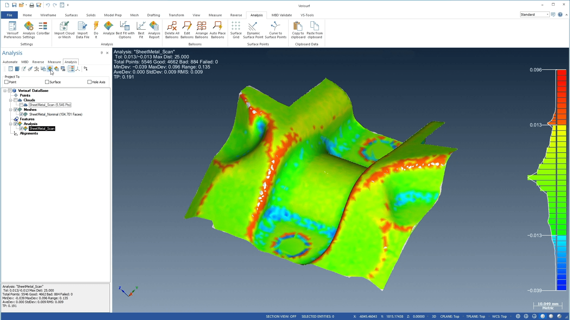
When it comes to inspecting contours that are not primitive, geometric shapes, 3D CMM-type devices are necessary. Examples are airfoil shapes on aircraft, automobile body panels, all sorts of molded plastics, or any “organic” shape with contours.
PRIMITIVE SHAPES
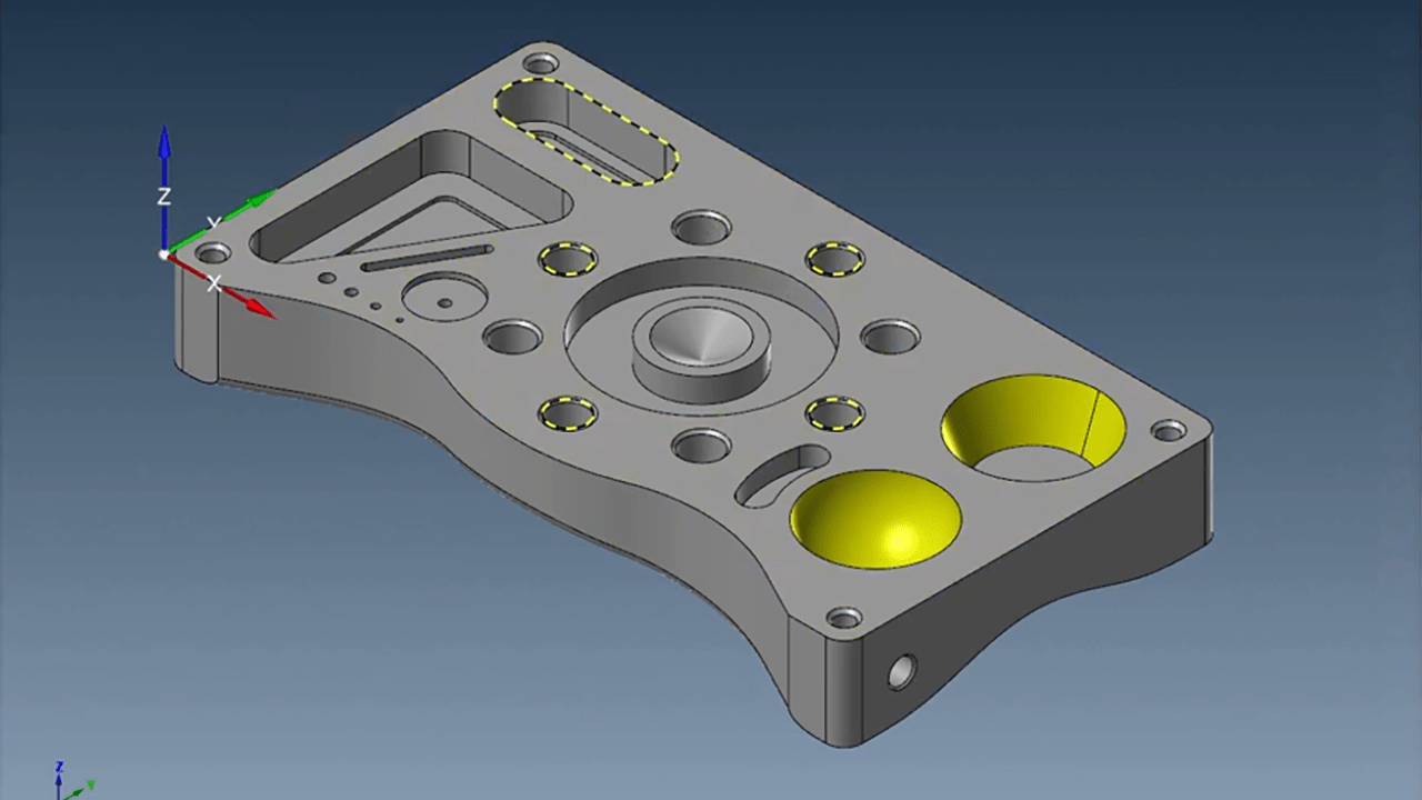
Hand-tool measurement gages, such as micrometers, calipers, gage pins, and height gages, are often used effectively for measuring primitive geometric shapes of a mathematical definition, such as planes, holes (cylinders), slots, cones, spheres, etc.
Hand-tool measurement gages, such as micrometers, calipers, gage pins, and height gages, are often used effectively for measuring. However, these tools fall short when it comes to inspecting contours that are not simple geometric shapes such as planes, holes (cylinders), slots, cones, spheres, etc. Examples of common non-geometrics include airfoil shapes on aircraft, automobile body panels, all sorts of molded plastics, or any “organic” shape with contours that have curvy, non-symmetrical shapes. In these instances, the solution falls to CMMs that can measure 3D coordinate points along part surfaces, comparing the measured points to the nominal, as-designed, CAD (computer-aided design) 3D model. This measurement type is referred to using principles of GD&T (geometric dimensioning and tolerancing) as Profile of a Surface.
For Profile tolerance “callouts,” measurement values are expressed as deviations rather than dimensions. Tolerance is defined by a range designated by “plus” and “minus” (+/-) limits. Measurement results are often reported both numerically and graphically and accompanied by a color map that highlights high and low regions of variance from the 3D model. Another frequent GD&T callout that is also difficult to measure with hand gages is hole location. This requirement, known as Position in GD&T (and sometimes informally as “true position”), is easily inspected and reported with 3D measuring devices.
Why Program a Manual Measuring Device?
CMM devices are essential for parts with complex contours, but they can even enhance productivity, accuracy, and process control for parts made up of simple shapes that are easily inspected with classic hand-measuring tools. For years, most manufactured parts have been designed digitally with CAD (computer-aided design). Therefore, a CAD model is usually available for other downstream activities. As long as a CAD model exists, it can be used to employ productive, modern manufacturing techniques and for computer-aided inspection (CAI).
Many benefits afforded to programmed, machine-driven CMMs can be realized for portable, manual devices as well.
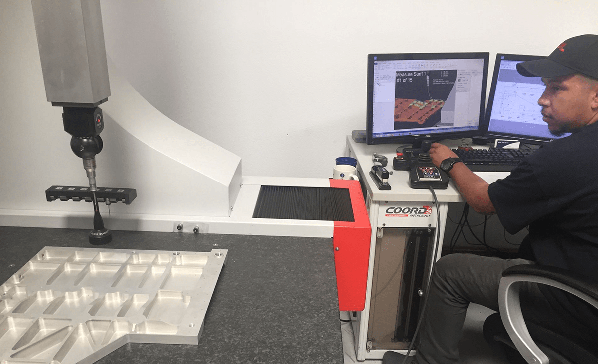
CMM-type devices come in many varieties, from motorized, computer-controlled, stationary CMMs designed to work in climate-controlled laboratories, to articulating, portable, manually-operated CMM “arms,” with five or six rotating joints and precision encoders. The portable CMM arm is designed to go anywhere in the shop or taken off-premises, where it can measure parts in place. It is also common to see them used in a manufacturing cell for maximized efficiency.
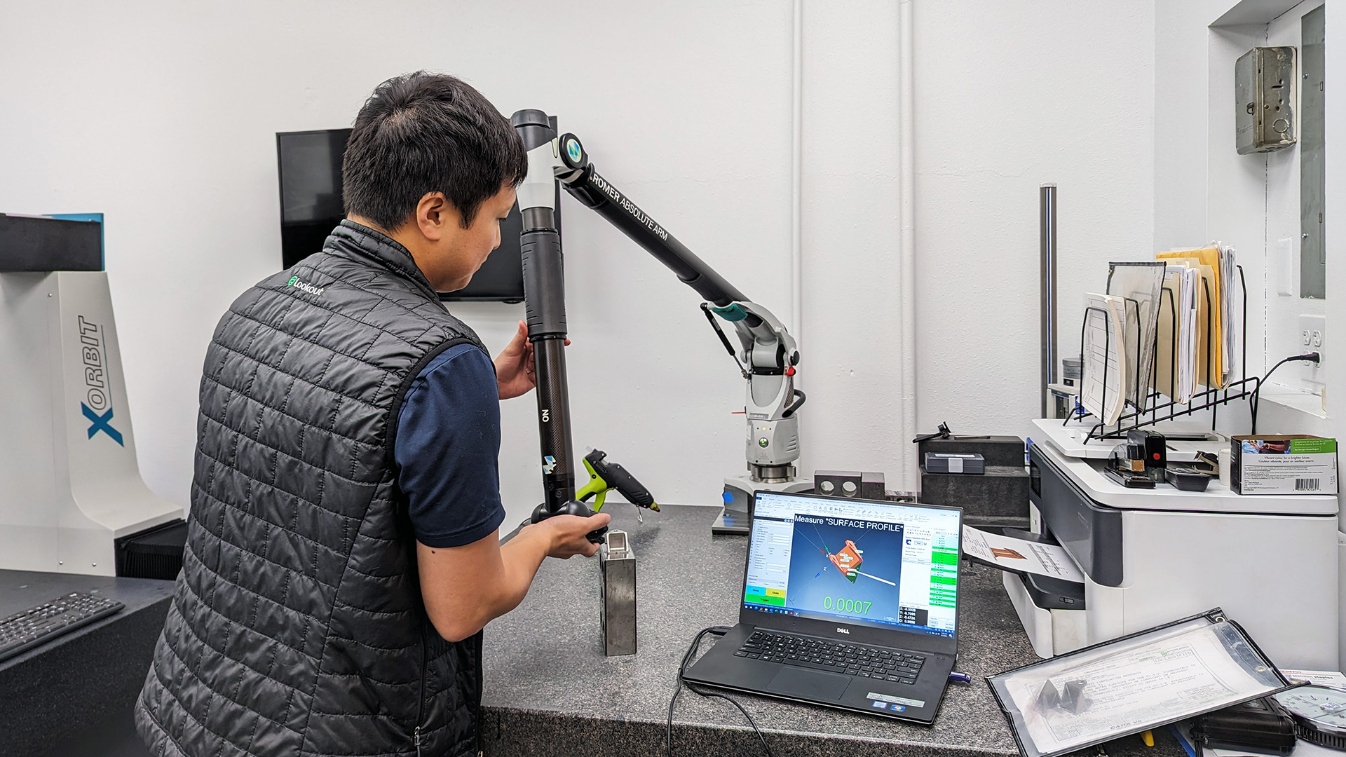
Both stationary, programmable CMMs and portable arms can be used for on-the-fly, unprogrammed measuring. However, programmable CMMs are mostly used in fully programmed and automatic measurement mode. CMM arms are more likely to be used in fully manual mode at the operator’s discretion, where planes, holes, and even profile points are measured by trained personnel.
However, this process can be improved upon by creating user-prompted, program-controlled, sequenced plans. These plans, or “programs,” are essentially digital work instructions (DWI).
Applications Where Portable CMMs Excel
One of the main reasons for which manual 3D measurement devices are chosen is portability. With a device such as a CMM arm, you can magnetically or clamp-mount them about anywhere and check the inspection article close to where it is manufactured or even on the machine that is making it. In most locations, no matter how adverse, with a wide variety of mounts, stands, carts, etc., they can be set up firmly, quickly, and ready to measure. Besides convenience, leaving the part in place may produce more accurate, quicker, and more legitimate measurements.
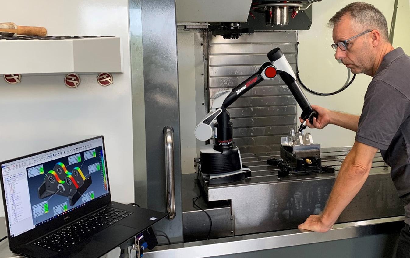
Portable devices also tend to be much less expensive both in acquisition and sustaining costs including long-term maintenance, calibration, and repairs. Most stationary, machine-driven CMMs require an environmentally controlled room, isolated to manage temperature, humidity, and vibration. For initial capital investment, stationary CMMs come at a much higher cost. The large, heavy granite tables, motors, linear scales, elaborate head systems, and complex controllers are some of the big ticket items. CMM arms have much fewer components, less elaborate control systems, and less complexity. In the early days of CMM arms, low accuracy made the cost difference irrelevant since they could simply not do the job. Therefore, stationary CMMs were the norm. Since then, new technologies have reduced the accuracy gap to the point where both portable devices and stationary CMMs are widely used. Many organizations rely on both solutions, one complementing the other.
Owners of both types of technologies will argue the benefits of one over the other. A common claim from stationary CMM owners is that with a programmed CMM, the operator can simply hit the “start” button and walk away, providing robot-like effectiveness. However, in most cases, when you see a CMM running, you will probably see an operator sitting alongside, watching it run through the measurement cycle. So, in reality, these machines are typically not used in a lights-out manner. CMM arms, with their six or seven-axis articulated joints, can often reach more measurement areas of the part easier and faster than a stationary CMM can. On fixed CMMs, parts often undergo multiple orientation changes, special fixturing, and complex programming to reach off-angle features for measurement.
Benefits for Portable CMM Arms and Other Manual 3D Measuring Devices
Speed – With a previously created, automated inspection plan, a user can inspect a part in a fraction of the time it takes to perform an inspection without one. All the workflow tasks are expedited, which include steps to study the drawing or model-based requirements, decide a measurement strategy, setup datums, nominals, tolerances, and relationships, take measurements, check the measurements, and format reports.
Efficiency – Especially for multiple-part inspections, the user will conduct each inspection in less time, moving on to the next workpiece in the batch with a comfortable rhythm and confident precision.
Process Control – An automated plan, based on the drawing requirements or model-based definition (MBD), ensures each part is measured the same way, datum structures are followed precisely, no measurement is missed, and each measurement is performed consistently This prevents variation due to breakdown of any of these factors. Data entry can often cause problems with repeated human input. The automated plan can reduce or eliminate that problem with no more transposition errors.
Personnel – The automated plan helps ensure that different personnel perform inspections precisely the same way, promoting repeatability and consistency. Assigning individuals capable of executing a pre-programmed plan is considerably easier than finding one with advanced skills and experience.
End Ambiguity Issues – Each job is unique, and interpretation from different operators can vary. Oftentimes, a user makes guesses about aspects of the measurement requirements. Data that is measured inconsistently can create big problems and may raise suspicions of “non-problems” or result in missing real issues that must be addressed.
Eliminate Variability – All parts measured with the same nominals, number of points, in the same spots, same probe compensation, same tolerances, same datums, and per exact MBD and/or drawing requirements, minimizes variability to nearly non-existent.
Reliable & Consistent Digital Records – A consistent digital record aids decision-makers and troubleshooters by improving reliability and traceability, and it is also available for forensic research if needed later. A maintained record that details how the part was inspected can further enhance manufacturing processes at any stage of the product lifecycle.
Cost Savings – Portable, manual CMMs such as articulating arms are less expensive in both purchase price as well as annual maintenance and calibration costs when compared with motorized, stationary CMMs. The machine, compressed air equipment, environmental lab, probes, and fixturing, all incur greater maintenance costs for stationary CMMs versus CMM arms.
Automation for Large Volume Measurement and Computer-Aided Assembly
Portable CMM Laser Trackers like the Hexagon Leica Absolute Laser Tracker AT960 are popular for measurement and computer-aided assembly of large parts and assemblies such as aircraft and automotive tooling.
Portable CMM Laser Trackers are popular for measurement and computer-aided “build” of large parts and assemblies such as aircraft and automotive tooling. Other industries where they are essential include shipbuilding, power generation, and industrial machinery. Laser trackers, capable of measuring within a few thousandths of an inch over 100 ft. distance and more, provide indispensable precision and efficiency.
In their earlier days, laser trackers were often run by two technicians. Typically, one person would handle the tracker ball, a.k.a. the SMR or “corner cube,” and another would handle the software from the computer workstation. While operational features like “Smart Point” (a.k.a. stable point) and remote mouse devices can improve single-operator tasks, an automated plan can control and sequence a more efficient inspection workflow. In addition, an automated plan tailored to laser tracker operation offers many benefits. Unlike CMM arms, the tracker ball has no buttons, and the frequent need to be far from the computer complicates manual control, requiring many individual steps to be engaged by numerous individual strokes on the keyboard.
With an automated plan, each measurement can “solve” or finish automatically and efficiently continue to the next point or feature measurement. Verisurf software automatically adds custom views as the plan builder creates the plan, which is essential for the operator to see where they are being prompted for the subsequent measurement. There is no need to take photos and load image files for this to occur. Verisurf uses automatic views of the CAD model, therefore eliminating the need for images to show the work sequence. (Note: Sequenced photo prompts and popup instructional dialogs, and input fields are available in Verisurf AUTOMATE as required.)
With automated plans for laser trackers, an operator can simply select the “run” button and proceed through the job with only the tracker ball in hand. In addition, six-DOF probes (6 degrees of freedom probes) can add further efficiency with their buttons that can be used and customized to step through the plans. They can execute commands like UNDO or FINISH and provide easier access to other features while out of sight from the tracker beam.
Embracing Model-Based Definition (MBD)
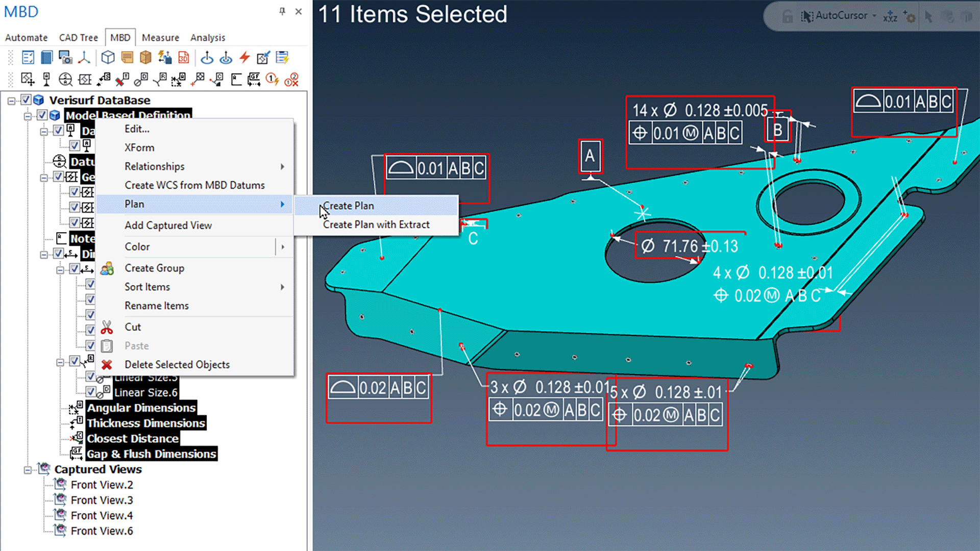
Embedded, associative MBD (Model-Based Definition) with interactive GD&T in Verisurf software.
Model-based definition is a manufacturing lifecycle methodology where the 3D CAD model is designated as the controlling authority for part design, shape, dimensions, processes, quality control, sub-contracts, and GD&T (geometric dimensioning and tolerancing) for manufactured parts and assemblies. Classic design practices relied upon 2D drawings (a.k.a. blueprints). MBD embraces the 3D model as part of “the digital thread” for product definition. Leading the way to a single, designated “master” for the data has been the aerospace industry, where the need for safety of flight, and removal of ambiguities where 2D drawings and the 3D CAD model differ. Or at least, when they differ or are not clear, the legitimate final authority is placed on the CAD model. Eliminating 2D drawings and other means of product definition is not always possible or feasible. Therefore, MBD has the distinction of being the final authority.
Today’s modern approach to MBD looks to embed GD&T and other key processes in the CAD model, making it associative, or “semantic,” whereby it is directly connected to geometries in the model. Unfortunately, it is still common to see GD&T that is not associative but is merely displayed as text or lines and curves disconnected from geometries, therefore unable to be applied automatically for inspection or other processes. Verisurf software has built-in MBD functionality for these cases, allowing users to create and associate GD&T with the CAD entities fully. With MBD, the CAD model conveys the tolerances and controls from the CAD system, conveying it to CAM (computer-aided manufacturing) and CAI (computer-aided inspection) aspects involved in the product lifecycle.
Verisurf uses MBD automatically for primary GD&T functions such as Profile and Position, applying tolerances and controls directly. This eliminates the need to interpret drawings and negates the possibility of transposition errors. The result is both time savings and improved process control. Automated plans controlling manual device inspection and the application of interactive MBD establish a fully digital thread for design, manufacture, and quality control.
Fulfill FAI First Article Inspection and PPAP
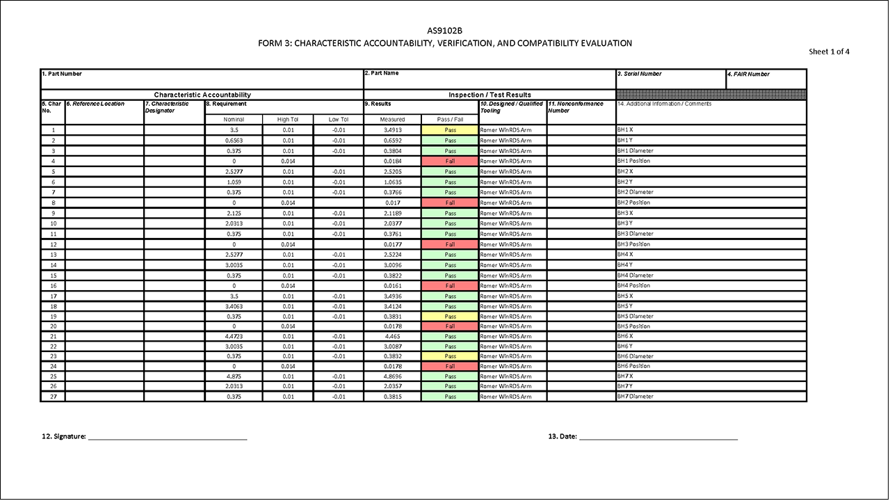
First Article Inspection (FAI) (per SAE AS9102 specification) and PPAP (as defined by the Automotive Industry Action Group AIAG) are requirements especially compulsory in aerospace and automotive industries in the early production cycle to verify parts are manufactured, inspected, and evaluated against the design requirements, ensuring that production processes can produce good parts before an entire production run begins. These requirements have very strict rules with strict specifications for the inspection processes and documentation.
Automating plans for FAI and PPAP, even for small quantities, provides better controls for inspection, ensures specifications and GD&T constraints are followed, and ensures consistent 3D traceability. Automated plans will convey an organization’s commitment to controlled processes that impress their customers and process auditors.
Scanned Data Processed Offline with Automated Plans
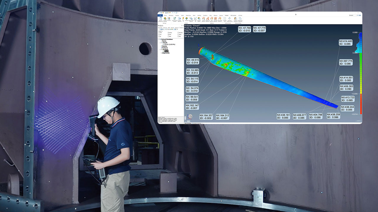
Inspection plans can be automated for manual and portable scanning devices, with all the control and efficiency benefits of contact probing devices. Software such as Verisurf AUTOMATE, can be used to create automated plans that will extract measurements from a scanned point cloud or 3D mesh.
Scanning is typically achieved with less upfront programming and expense with an arm or handheld scanner than programming a CMM or robot. CMMs and robots lend themselves more to high-volume scanning since the extensive programming and prove-out time can be amortized across high-quantity production runs.
Automated programs (Verisurf) can automatically extract measured features and apply nominal values, tolerances, and datum referencing callouts, quickly and reliably. Scanning can provide benefits when there is a lot of data to be acquired for complete coverage of complex parts, especially contoured profiles. It can also be the preferred inspection method with sensitive parts when it is best not to contact the part by contact probing.
Scanned Data Inspection – Feature Extraction from Pointcloud
The QMS Inspection Plan – Required by Aerospace and International Standards
The aerospace AS9100 standard and ISO equivalent for aerospace QMS (quality management systems), including First Article Inspection requirements, make creating and maintaining an inspection plan for manufactured parts and assemblies mandatory. An automated inspection plan enabled by a portable or manual CMM device provides a modern, digital inspection plan to satisfy a significant requirement of the regulations.
Enhanced Supply Chain – Reliable and Consistent
Customers, buyers, and source inspectors greatly appreciate the controlled methodology that a portable CMM and automated inspection plans provide. Process control, the integrity of the digital thread, model-based definition, and an established system that is reliable and consistent will make any supplier stand out in a crowded field. Source inspectors can feel confident and make themselves look good by embracing the technology that runs like clockwork. The system can even be used as a sales and marketing tool, promoting the process that ensures that the customer’s parts will meet specifications and will have a reliable means of traceability. It can also help to hold on to existing contracts and strengthen customer-vendor relationships.
If one wanted to create and ensure maximum compliance with no arguments about quality, automated inspection plans could be supplied to vendors, and even a relatively inexpensive 3D measuring arm, ready-to-go for inspecting their parts. This may sound extreme, but it would expedite and remove all doubt about product compliance and would ensure consistent measurement data.
Easy No-Code Programming with Intuitive Visual Interactivity
Filling the Skills Gap
Portable CMM arms optimized with automated inspection plans offer relief from the pains of the current skills gap in manufacturing and quality control. Setting up the process and initializing the system is easy, and it has now become a reliable mainstay for many organizations. Some institute the process as a company-wide solution, and others set it up alongside traditional procedures, supplementing manufacturing work cells. It allows parts to be inspected by personnel with rudimentary skills and training. Users perform inspections quickly since they do not have to study drawings and callouts, racking their brains trying to devise a strategy for each measurement. With these plans, technicians with little training can run inspections quickly, repeatably, and with all the guardrails in place to ensure precision and productivity.
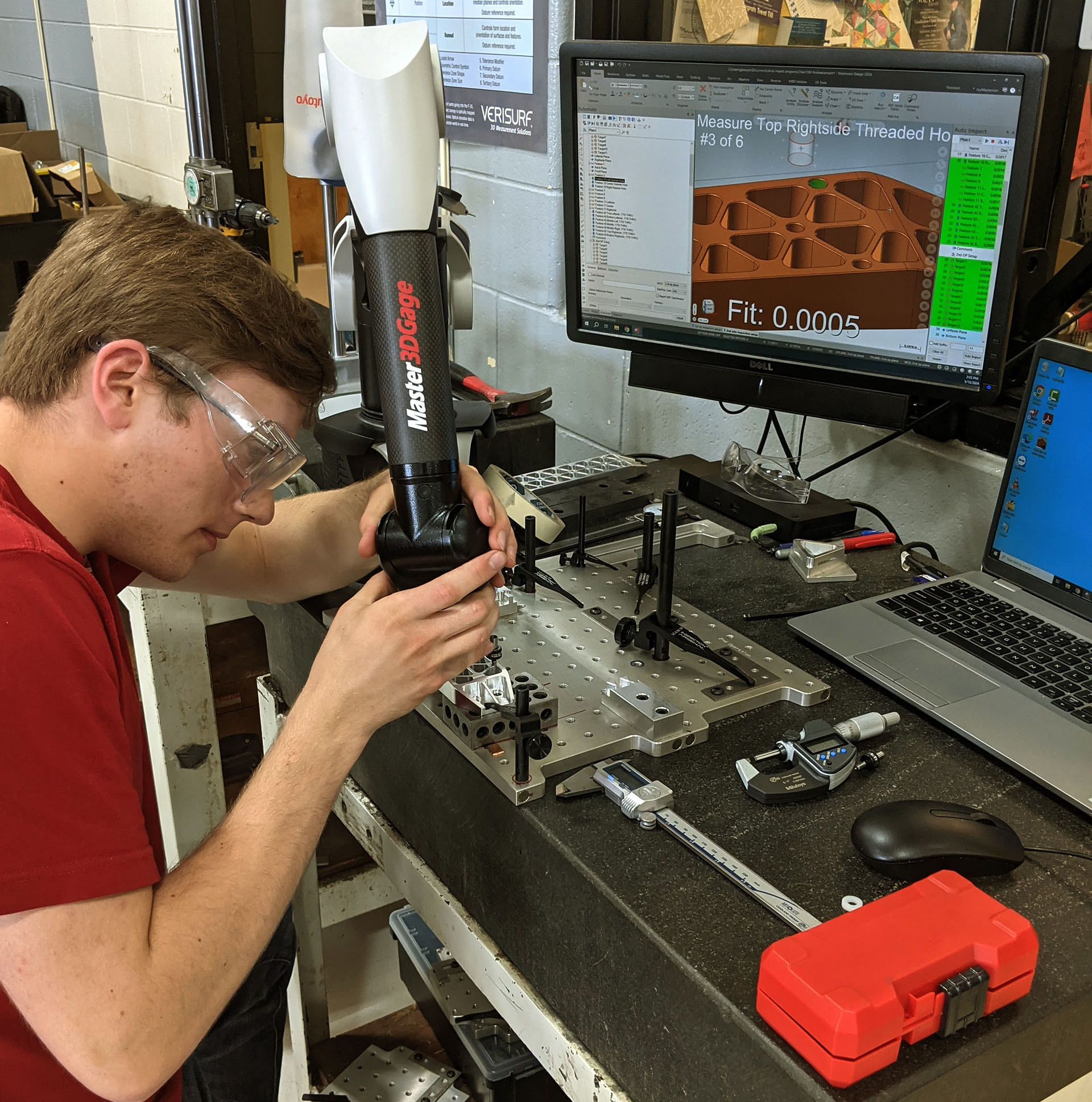
Courtesy Van Buren Tech (VB TECH), Lawrence, Michigan
Not only are inspections simplified for the operator, but plan creation requires little experience and training. A Quality or Manufacturing Engineer or Lead Inspector can create plans from CAD and drawings quickly and easily with Verisurf AUTOMATE software. It’s not a complex programming task and introduces fewer issues and restrictions than the more involved programming of motorized CMMs. With Verisurf software and its intuitive user interface and workflow, programmers can create plans without weeks or months of training. They are typically up and running in much less time than it takes to make a CMM programmer proficient on the industry’s most prolific software platforms. Verisurf, being built upon the world’s number one CNC programming (a.k.a. CAM) software, Mastercam, is being taught at many technical schools along with Mastercam. Whether filling inspection positions from within or from tech schools, this automated solution provides an easy path to implementation.
Portable CMM Inspection Automation Meets Quality 4.0 Objectives
Verisurf helps manufacturers implement Industry 4.0 objectives with Quality 4.0 technology that helps improve quality, reduce costs, and increase productivity.
Connectivity – Digital connection to all brands and models of CMMs extends the reach of “The Internet of Things” (IoT) smart factory.
Big Data Analytics – Inspection data populates first article inspection and production part inspection databases for statistical process control (SPC) and complete supply chain traceability.
Autonomy – Continuous inspection data can feed autonomous systems that identify trends and adapt manufacturing processes.
Simulation – Virtual 3D measurement visualization and simulation with “Cyber-Physical Digital Twins.”
To avoid being left behind as manufacturing organizations move forward in the age of Industry 4.0, the Fourth Industrial Revolution (4IR), a positive step towards digital connectivity and transformational technologies, is software automation of manually operated measuring systems. With tested and proven software platforms that enable the latest in 3D measurement devices, such as precision CMM arms, advanced non-contact scanners, and large volume 6DOF (six degrees of freedom) trackers, the gap is being filled between manual gages and paper drawings and high-cost, hands-off automation.
Author: Scott Knoche – Verisurf Software, Inc. (technical marketing & sales at Verisurf since 2002)

