Software Highlights – CMM Programming
DATUM REFERENCE FRAMES (DRFs)
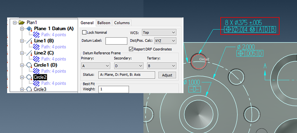
Drawings or CAD model Product Manufacturing Information (PMI) designate Geometric Dimensioning and Tolerancing (GD&T) callouts or “control frames” which set the rules controlling from where part features are to be measured or referenced. The controlling features are the datums, and the GD&T callouts tell which datums are to be used for referencing individual (or groups of) part features.
The GD&T Control Frame provides definition for the DRF
Using Datum Reference Frames (DRFs) in Verisurf AUTOMATE
Datum Reference Frames can be quickly and easily set up for Features, Analysis objects, and Constructs using the General Tab in the Details Pane of the Automate Manager.
Name – by default, feature names originate in the Measure Data Tree to populate the Reports Data List. Editing the name in the report does not affect the Measurement Data Tree. Names may also be edited directly in the data list.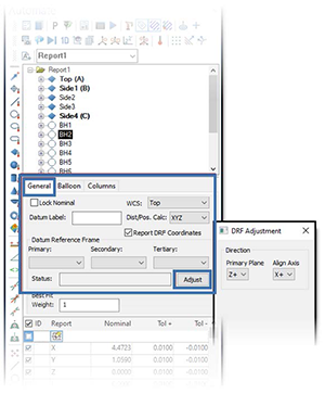
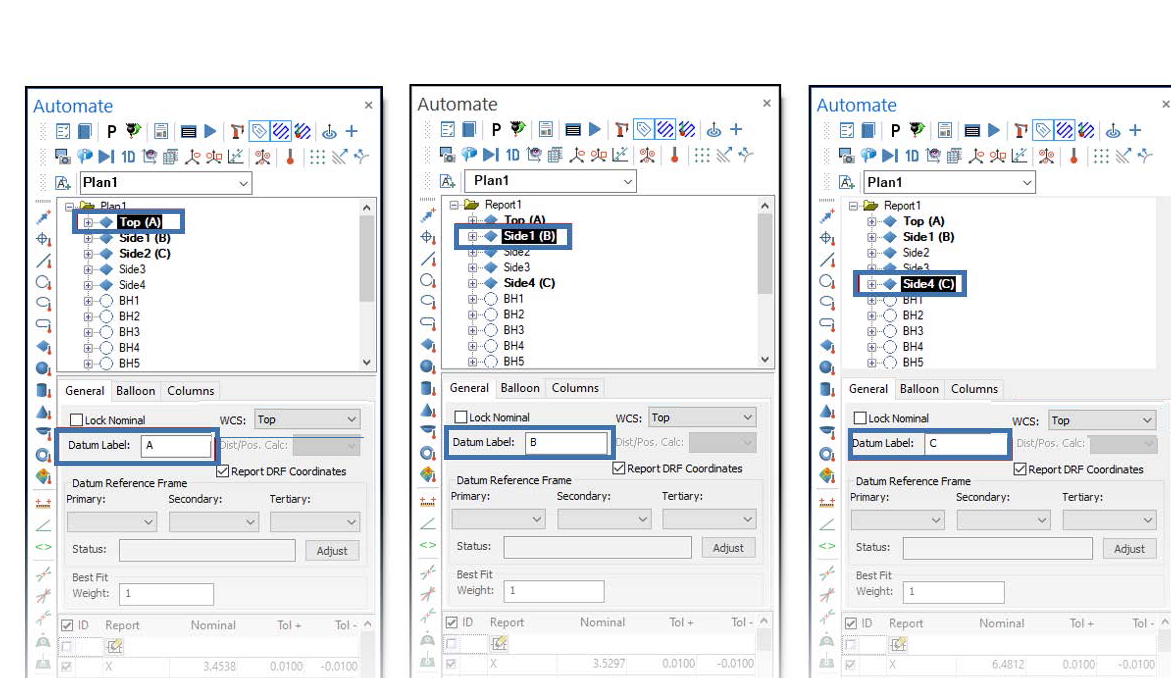
Datum Label – allows features in the name field to be tagged as a Datum to use with the Datum Reference Frame tool in the Report Manager.
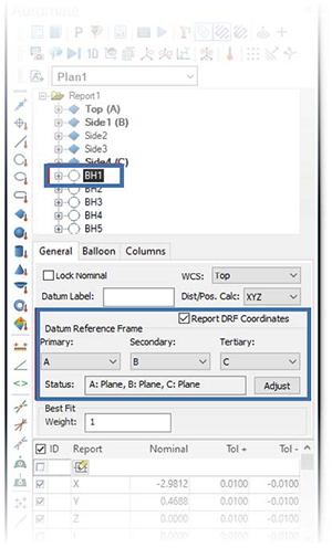
Datum Reference Frame – select and associate features to datums using drop-down menus for the Primary, Secondary, and Tertiary datums.
Status – displays the current feature datum association in the Name data field.
Adjust – opens a dialog to allow changes to current Status components.
In the example below, no Datums influence the coordinate value for BH1; and the WCS is set to Top.
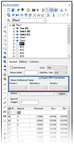
By assigning Datum Labels to features, you build a Frame within WCS Top.
 To assign Datum Frame orientations to other Data List features, select them and use the Primary, Secondary, and Tertiary drop-downs.
BH1 now displays coordinate values relative to the Data Reference Frame while the Global WCS remains in Top.
Select Report DRF Coordinates to display the Datum Reference Frame association in the Report Column Header.
DRFs and Analysis Objects (surface points groups)
Analysis object results are projected to Nominal CAD entities when the DRF is applied or edited. The Analysis object may require Re-Projection due to the CAD Nominal value shift.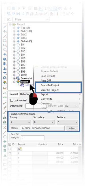
Force Re-Project
When the DRF of an Analysis object has been changed, this function becomes available in the Analysis object speed menu. When selected, the Projection is performed based on the current DRF setting.
Clear Re-Project
Available in the Analysis object speed menu after Force Re-Project has been used, you can return the Analysis object to the previous state.
Auto DRF
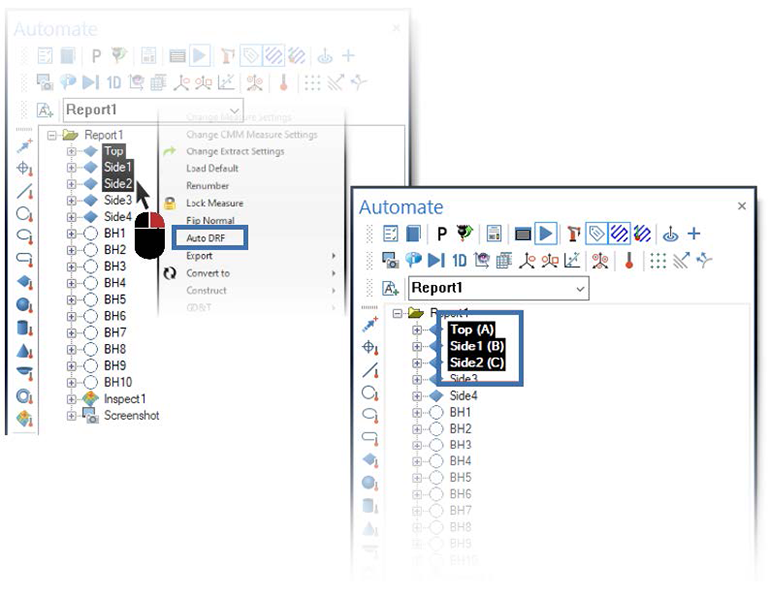
Quickly define Datums based on the selection in the Data List. Datums are assigned alphabetically (A, B, C) based on the Data List order.
Clear DRF
Select this to clear previously assigned DRF from selected Features in the Data List.

