Intelligent Model Based GD&T for Inspection
A PRACTICAL FIRST STEP TOWARD COMPREHENSIVE MODEL-BASED DEFINITION
The central concept embodied in model-based definition (MBD) is that the 3D CAD model provides the detailed product information necessary for all aspects of the product definition. Engineers have wanted to harness the power of MDB for years.
A true implementation of MBD is much broader than model-based GD&T (Geometric Design and Tolerancing), yet both rely on the CAD model as the nominal authority. Associative GD&T datums confer geometric design constraints and provide information to manufacture and verify part quality against the CAD model. MBD takes this information downstream to support comprehensive Product Lifecycle Management (PLM) applications.
For both Model-Based GD&T and broader MBD applications, all dimensions and tolerances are pulled from the 3D model instead of 2D paper drawings. Making the model the authority removes ambiguity, conflict, and doubt that arise when drawings and models co-exist. With authority bestowed on the model, errors that result from referencing an incorrect source are eliminated, making processes more efficient—no more searching to find correct revision levels.
In the context of the enterprise, the benefits are many and diverse. MBD is the single information source to build and support products, and it integrates into processes from cradle to grave. To summarize the benefits of providing definitions for operations throughout the product lifecycle, one must only look at the goals of leading aerospace companies, automotive manufacturers, and others when they began their pursuits of MBD:
- Process control
- Safety
- Reduced scrap
- Accelerate time-to-market
- Decrease time and expense
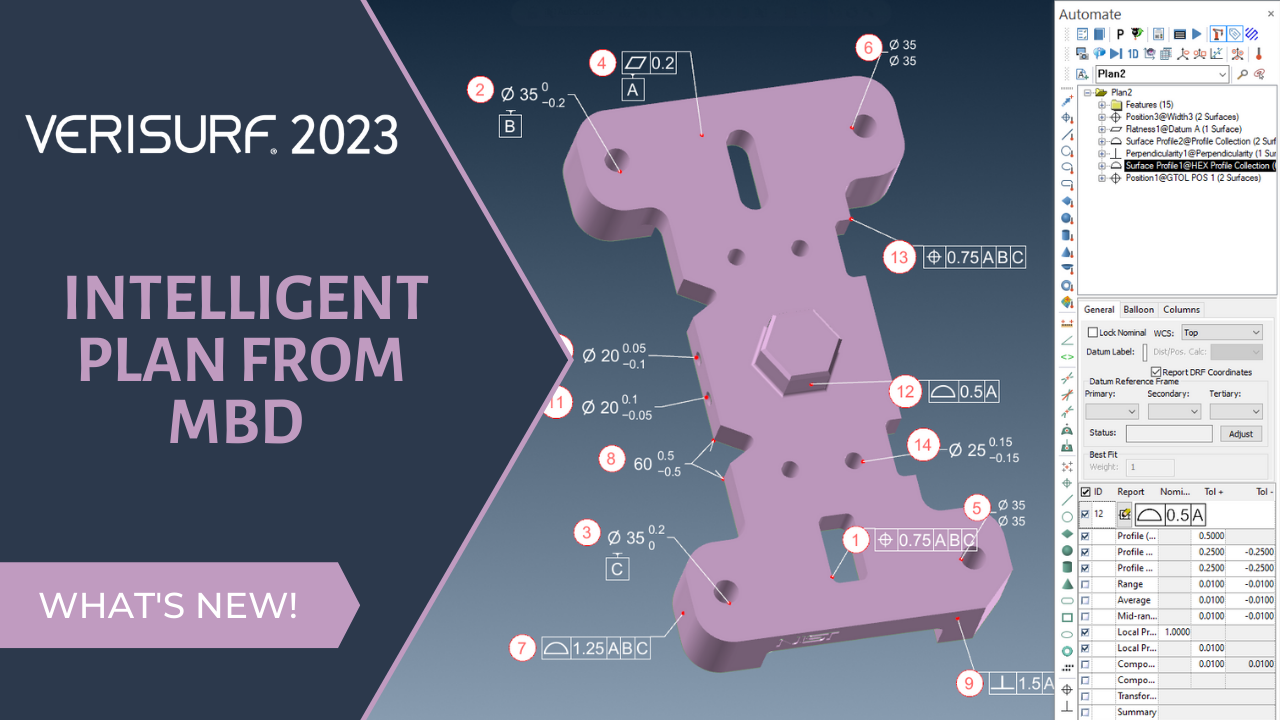
Verisurf software automates inspection plan programming using intelligent model-based GD&T. Verisurf’s MBD-to-Plan feature automatically recognizes features and assigns datums and tolerances for inspection.
There is a common misconception that MBD is synonymous with GD&T. In some circles, using model-based GD&T is incorrectly considered a full implementation of MBD. While model-based GD&T is a necessary component of MBD, much more information is needed for a complete enterprise deployment of model-based definition. With that understanding, model-based GD&T is a great place to start when moving toward a model-based enterprise. It moves the CAD model from being design-only to empowering efficient manufacturing as well. It offers many advantages, such as automating and validating simulation, manufacturing, and inspection. With all it offers, model-based GD&T will put you on track with MBD compliance initiatives for OEMs and tiered supply chain manufacturers.
GD&T
GD&T is a universal design language rigorously studied and applied by thousands of manufacturers worldwide. Last updated in 2018, GD&T is widely considered by mechanical engineers to be an essential tool for communicating design. The latest update to GD&T is the ASME Y14.5-2018 standard, which includes changes like new symbols for tolerance zones, datum reference frames, and guidance on using GD&T within 3D CAD models; the most significant change being a more straightforward definition of datum stabilization protocols to eliminate ambiguity.
Today, most CAD designs are done in 3D, but not all manufacturing suppliers receive CAD models with intelligent GD&T data. There are two formats of GD&T data. Non-semantic GD&T refers to tolerances that are not adequately defined according to the established standards (like ASME or ISO), meaning they might not convey the intended manufacturing constraints, while semantic GD&T indicates tolerances that are accurately annotated and follow the standard logic, providing an unambiguous interpretation for manufacturing purposes; essentially, semantic GD&T is the correct way to apply GD&T symbols and annotations according to the standards, while non-semantic GD&T could lead to confusion or misinterpretation by manufacturers.
Non-semantic GD&T is also commonly called display-only GD&T. As a result, humans must interpret the GD&T information. The display-only format is similar to typing a mathematical equation in Microsoft Word. It conveys information, but the computer cannot use it in a calculation. In conversation, this approach is commonly referred to as “decorating the model.”
What makes the effort of annotating intelligent GD&T on the 3D model worthwhile? The answer is simple and the same as that for MBD — data leveraging. Leveraging the data throughout the process saves time and improves results while at the same time avoiding any investment in 2D drawings. The Model-based GD&T data provides access to powerful tools that preserve accuracy, accelerate processes, and deliver “artificial intelligence” in manufacturing and inspection applications.
MODEL-BASED GD&T FOR INSPECTION
GD&T defines the standards of quality. Inspection confirms that the quality standards are being met. Data flows directly into the inspection software if:
- GD&T representation is available.
- Inspection software can import this data from the native CAD system.
- Or if intelligent GD&T data is unavailable, can it be added and associated with the 3D model by the inspection software?
When these conditions are satisfied, inspection planning, measuring, and reporting become simple, fast, effective, and error-free. Model-based GD&T for inspection is the functionality that addresses inspection against a CAD model independent of how or where tolerancing is defined. A 3D CAD model is imported and used as the basis for inspection planning and dimensional variance. The model provides all nominal dimensions. GD&T annotations to support a digital inspection workflow can also be captured from 2D drawings, including PDFs.
AUTOMATED INSPECTION PROGRAMMING
One of the most significant benefits of working with Model-Based GD&T for inspection and measurement is automation. For example, Verisurf software automates inspection plan programming using intelligent GD&T. Parts with complex GD&T callouts, such as under-constrained references, composite position, and separate and simultaneous requirements, are challenging to program and report. Verisurf uses available model-based GD&T to create an inspection plan, automatically recognizing features with simultaneous requirements, grouping them into a single callout, and applying the necessary alignment. Plans are assigned datums and tolerances, including composite tolerance, and are configured for the specified material condition.
“At Verisurf Software, we recognize the growing use of MBD and 3D annotation. Verisurf software accommodates intelligent ‘semantic’ GD&T and display-only ‘non-semantic’ GD&T. Intelligent GD&T data is imported directly into the Verisurf software as part of the 3D model. In the case of display-only annotations, the quality or manufacturing engineer can add the GD&T annotations to the 3D model within Verisurf,” said Nick Merrell, Executive Vice President of Verisurf Software, Inc.
Verisurf Intelligent Model-Based GD&T data can be:
- Imported from or created on any 3D CAD/CAM model.
- Parts can be verified within tolerances as part of an automated manual or programmable inspection routine providing repeatable process control.
- Inspection reports are created in real-time and can be output in various industry formats.
“Verisurf software has Model-Based GD&T Inspection at its core, making it possible to import Model-Based GD&T data, create it, if necessary, inspect it, and report on it,” Merrell added.
When the information is imported from the native CAD system as a semantic GD&T representation, there is a correct model-based implementation, and the authority of the dataset is preserved. The same applies if non-semantic GD&T ‘display-only data’ is interpreted and manually entered into the inspection application. In both scenarios, there is no investment in creating or maintaining 2D drawings.
PROCESS
- Open the 3D CAD file using a model-based GD&T-featured metrology software. All intelligent GD&T data will be included.
- If necessary, manually add display-only GD&T specifications to the 3D model with the metrology software application.
- Create an automated manual or programmable inspection plan as supported by the metrology software application.
- CAD-based metrology software typically allows the addition of notations, guidelines, or controls specific to the supplier’s manufacturing process and needs that may not have been considered earlier.
- Run the inspection process. The software should support and operate all digital metrology devices, such as programmable CMMs, scanners, portable arms, and trackers.
- The software prompts the operator to select reference points for aligning the physical part to the CAD model. GD&T datum points can be set as inspection targets. The software prompts the operator with onscreen targets as they execute the plan.
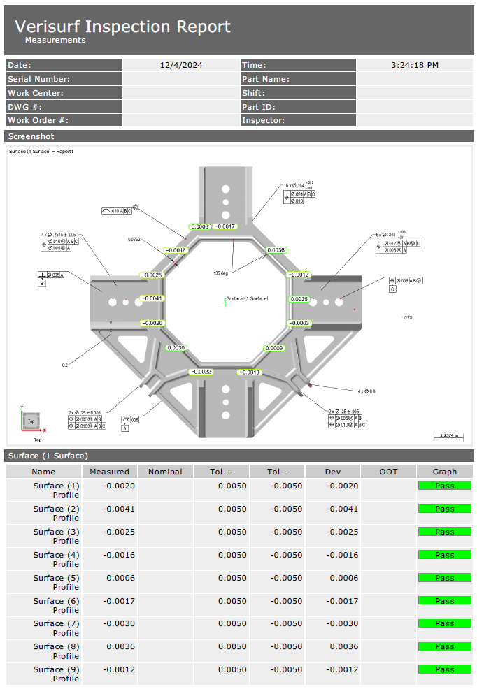
- Results are displayed with graphics and text as measurements are taken. Immediate feedback shows the measured value and deviation, showing “pass” or “fail” per the prescribed GD&T allowance. This is also documented in a pre-formatted inspection report, eliminating data entry and manual calculations.
The quality assurance process becomes automated when the product definition flows from the model and through inspection. Conflict and transportation errors are eliminated, interpretation is unnecessary, and only basic skills are needed. This is in stark contrast to a print-based CMM inspection operation. Model-based GD&T makes digital inspection a practical and realistic alternative for shops facing workforce development challenges.
CLOSING THE LOOP
Model-based GD&T inspection truly closes the loop. It bounces QC data against the 3D authority in real-time. This makes inspection results more valuable and straightforward. It maintains connection without failures in interpretation or instances of ambiguity, preserving true design integrity.
Model-based GD&T inspection provides repeatable process control. Inspection feedback offers insight into any deviations, providing manufacturing engineering with data to help determine the root cause of production issues. Inspection reports and supporting data can be passed directly to product lifecycle applications across the manufacturing enterprise.
It has long been said that you cannot improve what you cannot measure. Model-based GD&T inspection fosters improvement by making it feasible to measure more, measure faster, and measure better.
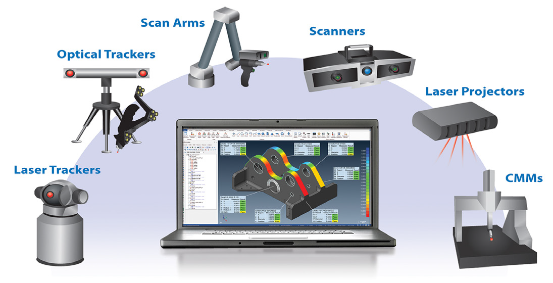
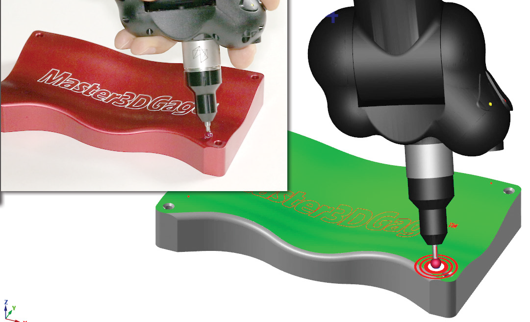
Left – Verisurf software is model-based and operates all programmable CMMs, arms, scanners, and trackers.
Right – Verisurf software combines cyber physical interaction for real time alignment, inspection, and reporting.

