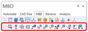
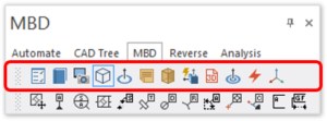
The Verisurf Model-Based Definition (MBD) Manager includes all of the Tools and Utilities listed below. MBD annotations appear in the Operations Manager tree and in the graphics area and can easily be added, edited, or deleted.
MBD Tools:

Verisurf MBD Operations Manager: Tools top menu

Reposition an existing MBD callout frame.

Label a feature as a datum.

Label a feature with a datum target.

Control frame – assign an MBD (GD&T) callout to a feature.

Apply a distance dimension between 2 points or parallel planes.

Apply a dimension to a part thickness.

Apply a dimension to hole diameters.

Apply a hole radius dimension.

Apply a dimension between planar and angular surfaces.

Dimension a point coordinate.

Display the shortest distance between a point and a CAD surface.

Place an annotation without a leader to a feature.

Use surfaces or CAD points to define Gap Flush dimensions.
MBD Utilities:

Verisurf MBD Operations Manager: Utilities top menu

Open Verisurf Preferences – Display Settings dialog.

Open the MBD Reference Manual.

Screenshot – Capture graphics window images to be used in the Report Manager or Microsoft Paint.

Remove hidden lines to improve the clarity of MBD callouts.

Create a circle from a hole.

Add model-specific (Part) notes or general notes that persist across all models.

Minimum Bounding Box; used to assess minimum material required for machining.

Flip and correct Surface Normal direction for Inspect/Build or Surface Analysis.

Create a 3D PDF file that includes MBD callouts, Datum Targets, and Analysis results.

Create hole axes, vectors, arcs, or points on all visible circular entities.

Select a surface – including contiguous surfaces.

Toggle display of the WCS axis symbol at the WCS origin.

